
Page 175 - Practical Power System and Protective Relays Commissioning
P. 175
Power System Fault Analysis Chapter | 16 175
constructed, starting from an infinite source and leading to the fault posi-
tion. All values of impedance used to construct the network must refer to
the same MVA base. For consistency, always use the percent impedance to
a base of 100 MVA.
If the fault being considered is a three-phase fault, then there will only be
positive-sequence quantities present, therefore only positive-sequence impe-
dances need to be considered.
The impedance to the fault can now be calculated, and from this the fault
current can then be calculated (I F ). The fault current in other parts of the net-
work can be derived using network analysis techniques, with the fault current
at the relay point.
If the protection relay is an impedance measuring type (i.e., distance pro-
tection) then it may only be necessary to calculate the impedance to the
fault.
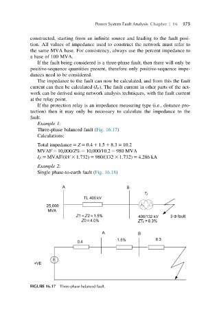
Example 1:
Three-phase balanced fault (Fig. 16.17)
Calculations:
Total impedance 5 Z 5 0.4 1 1.5 1 8.3 5 10.2
MVAF 5 10,000/Z% 5 10,000/10.2 5 980 MVA
I F 5 MVAF/(kV 3 1.732) 5 980/(132 3 1.732) 5 4.286 kA
Example 2:
Single phase-to-earth fault (Fig. 16.18)
FIGURE 16.17 Three-phase balanced fault.