
Page 219 - Practical Power System and Protective Relays Commissioning
P. 219
Protection Relays Chapter | 18 219
For close-up faults near the remote end at busbar B, the relay can under-
reach as the relay voltage V R will be very small, and due to VT and CT
errors, the relay will see the internal zone fault as a fault outside the line
A B. This will be for transmission lines with a high SIR ratio, as shown in
Fig. 18.6.12B. There will be no problem for transmission lines with a low
SIR ratio, as shown in Fig. 18.6.12C.
18.6.4.2 Distance Protection Setting for Parallel Lines
When we set a distance relay with two parallel transmission lines or a local
infeed at the remote end, special consideration should be given, as explained here
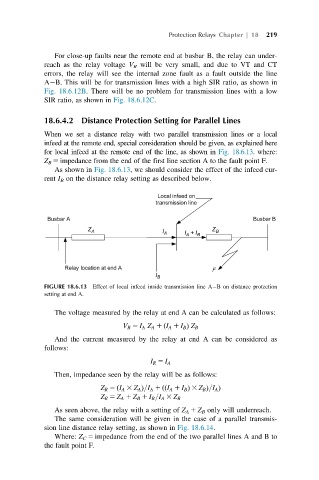
for local infeed at the remote end of the line, as shown in Fig. 18.6.13.where:
Z B 5 impedance from the end of the first line section A to the fault point F.
As shown in Fig. 18.6.13, we should consider the effect of the infeed cur-
rent I B on the distance relay setting as described below.
FIGURE 18.6.13 Effect of local infeed inside transmission line A B on distance protection
setting at end A.
The voltage measured by the relay at end A can be calculated as follows:
V R 5 I A Z A 1 I A 1 I B Þ Z B
ð
And the current measured by the relay at end A can be considered as
follows:
I R 5 I A
Then, impedance seen by the relay will be as follows:
ð
Z R 5 I A 3 Z A Þ=I A 1 I A 1 I B Þ 3 Z B Þ=I A Þ
ð ð
Z R 5 Z A 1 Z B 1 I B =I A 3 Z B
As seen above, the relay with a setting of Z A 1 Z B only will underreach.
The same consideration will be given in the case of a parallel transmis-
sion line distance relay setting, as shown in Fig. 18.6.14.
Where: Z C 5 impedance from the end of the two parallel lines A and B to
the fault point F.