
Page 223 - Practical Power System and Protective Relays Commissioning
P. 223
Protection Relays Chapter | 18 223
FIGURE 18.6.19 Trip logic of the permissive underreach transfer trip scheme.
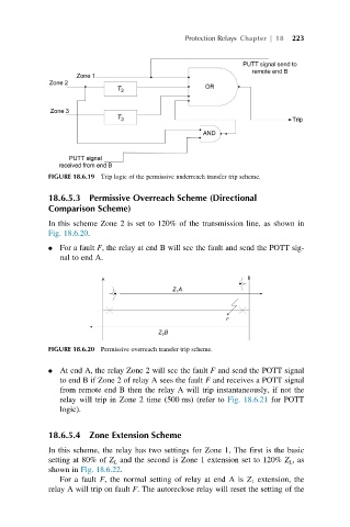
18.6.5.3 Permissive Overreach Scheme (Directional
Comparison Scheme)
In this scheme Zone 2 is set to 120% of the transmission line, as shown in
Fig. 18.6.20.
For a fault F, the relay at end B will see the fault and send the POTT sig-
nal to end A.
FIGURE 18.6.20 Permissive overreach transfer trip scheme.
At end A, the relay Zone 2 will see the fault F and send the POTT signal
to end B if Zone 2 of relay A sees the fault F and receives a POTT signal
from remote end B then the relay A will trip instantaneously, if not the
relay will trip in Zone 2 time (500 ms) (refer to Fig. 18.6.21 for POTT
logic).
18.6.5.4 Zone Extension Scheme
In this scheme, the relay has two settings for Zone 1, The first is the basic
setting at 80% of Z L and the second is Zone 1 extension set to 120% Z L ,as
shown in Fig. 18.6.22.
For a fault F, the normal setting of relay at end A is Z 1 extension, the
relay A will trip on fault F. The autoreclose relay will reset the setting of the