
Page 227 - Practical Power System and Protective Relays Commissioning
P. 227
Protection Relays Chapter | 18 227
Phase-to-phase faults;
For correct measurement of Z L1 we should have the following inputs:
Voltage input 5 phase to phase voltage;
Current input 5 difference between currents in the faulted phases.
Fault Voltage Applied Current Applied
A-B V AB I A -I B
B-C V BC I B -I C
C-A V CA I C -I A
Phase-to-earth faults
For correct measurement of Z L1 we should have the following inputs:
Voltage input 5 phase to earth voltage on faulted phase;
Current input 5 current in faulted phase 1 a proportion of the residual
current depending on the ratio of zero to positive sequence impedance
of the line.
Fault Voltage Applied Current Applied
A-E V AE I A 1 K N 3 I RES
B-E V BE I B 1 K N 3 I RES
C-E V CE I C 1 K N 3 I RES
Where K N 5 residual earth fault compensation factor 5 ðZ L0 2 Z L1 Þ ,
3Z L1
I RES 5 residual current 5 (I A 1 I B 1 I C ).
In general practice as a guide K N for overhead lines 5 0.6 and for cables
K N 5 0.3.
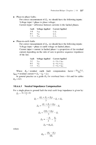
18.6.6.1 Neutral Impedance Compensation
For a single phase to ground fault the total earth loop impedance is given by:
Z T 5 ðZ 1 1 Z 2 1 Z 0 Þ
3
ðZ 1 1 Z 2 1 Z 0 Þ
Z T 5 5 Z 1 1 Z N
3
ðZ 1 1 Z 2 1 Z 0 Þ
Z N 5 Z 1
3
ð2Z 1 1 Z 0 Þ
Z N 5 2 Z 1
3
2 Z 1 Z 0
Z N 5 1
3 3
Z N 5 K N Z 1
where
ðZ 0 2 Z 1 Þ
K N 5
3Z 1