
Page 224 - Practical Power System and Protective Relays Commissioning
P. 224
224 Practical Power System and Protective Relays Commissioning
FIGURE 18.6.21 Trip logic for relay at end A.
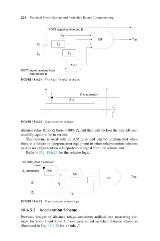
FIGURE 18.6.22 Zone extension scheme.
distance relay R A to Z 1 basic 5 80% Z L and then will reclose the line AB suc-
cessfully again to be in service.
This scheme is used with an A/R relay and can be implemented when
there is a failure in teleprotection equipment in other teleprotection schemes
as it is not dependent on a teleprotection signal from the remote end.
Refer to Fig. 18.6.23 for the scheme logic.
FIGURE 18.6.23 Zone extension scheme logic.
18.6.5.5 Acceleration Scheme
Previous designs of distance relays sometimes utilized one measuring ele-
ment for Zone 1 and Zone 2, these were called switched distance relays, as
illustrated in Fig. 18.6.24 for a fault, F.