
Page 221 - Practical Power System and Protective Relays Commissioning
P. 221
Protection Relays Chapter | 18 221
FIGURE 18.6.15 Effect of weak infeed in the permissive overreach transfer trip distance relay
scheme.
18.6.5 DISTANCE PROTECTION TELECOMMUNICATION
SCHEMES
As we can see previously, there is still 20% of the line section not protected
instantaneously as we set Zone 1 to reach only up to 80% of the line for the
reasons explained above. To overcome this problem we use telecommunica-
tion schemes which utilize a power line carrier, microwave radio signals, or
the most recent being fiber-optic cables to transfer the protection signals
through the transmission lines between both ends of the line to accelerate
tripping in this remaining part of the line (Fig. 18.6.16).
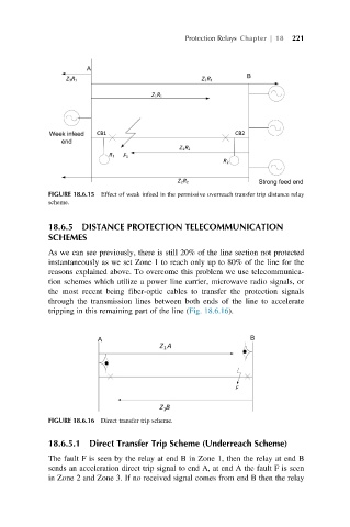
FIGURE 18.6.16 Direct transfer trip scheme.
18.6.5.1 Direct Transfer Trip Scheme (Underreach Scheme)
The fault F is seen by the relay at end B in Zone 1, then the relay at end B
sends an acceleration direct trip signal to end A, at end A the fault F is seen
in Zone 2 and Zone 3. If no received signal comes from end B then the relay