
Page 280 - Practical Power System and Protective Relays Commissioning
P. 280
274 Practical Power System and Protective Relays Commissioning
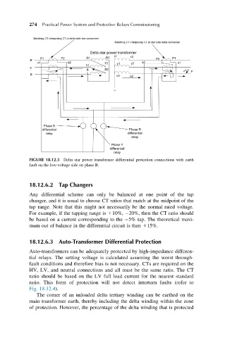
FIGURE 18.12.3 Delta star power transformer differential protection connections with earth
fault on the low-voltage side on phase B.
18.12.6.2 Tap Changers
Any differential scheme can only be balanced at one point of the tap
changer, and it is usual to choose CT ratios that match at the midpoint of the
tap range. Note that this might not necessarily be the normal rated voltage.
For example, if the tapping range is 110%, 20%, then the CT ratio should
be based on a current corresponding to the 5% tap. The theoretical maxi-
mum out of balance in the differential circuit is then 115%.
18.12.6.3 Auto-Transformer Differential Protection
Auto-transformers can be adequately protected by high-impedance differen-
tial relays. The setting voltage is calculated assuming the worst through-
fault conditions and therefore bias is not necessary. CTs are required on the
HV, LV, and neutral connections and all must be the same ratio. The CT
ratio should be based on the LV full load current for the nearest standard
ratio. This form of protection will not detect interturn faults (refer to
Fig. 18.12.4).
The corner of an unloaded delta tertiary winding can be earthed on the
main transformer earth, thereby including the delta winding within the zone
of protection. However, the percentage of the delta winding that is protected