
Page 335 - Practical Power System and Protective Relays Commissioning
P. 335
330 Practical Power System and Protective Relays Commissioning
20.2.1.2 Directional Overcurrent Relay Testing and
Commissioning
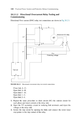
Directional Over current (DOC) relay test connections are shown in Fig 20.2.3:
FIGURE 20.2.3 Directional overcurrent relay test circuit connections.
Close link A C;
Open link A B;
Open link C D;
Open link 1 3;
Open link 2 4.
1. Repeat the same procedure to short circuit (SC) the current circuit for
each phase and inject current at the relay side.
2. Open the VT secondary circuit in isolating link terminals and inject the
voltage at the relay side.
3. Isolate the trip circuit by opening the links and connect the tester timer
stop points to the trip contact of the relay.