
Page 339 - Practical Power System and Protective Relays Commissioning
P. 339
334 Practical Power System and Protective Relays Commissioning
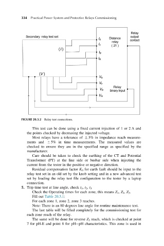
FIGURE 20.3.2 Relay test connections.
This test can be done using a fixed current injection of 1 or 2 A and
the points checked by decreasing the injected voltage.
Most relays have a tolerance of 6 5% in impedance reach measure-
ments and 6 5% in time measurements. The measured values are
checked to ensure they are in the specified range as specified by the
manufacturer.
Care should be taken to check the earthing of the CT and Potential
Transformer (PT) at the line side or busbar side when injecting the
current from the tester in the positive or negative direction.
Residual compensation factor K 0 for earth fault should be input to the
relay test set in an old set by the knob setting and in a new advanced test
set by loading the relay test file configuration to the tester by a laptop
connection.
5. Trip time test at line angle, check t 1 , t 2 , t 3
Check the Operating times for each zone, this means Z 1 , Z 2 , Z 3 .
Fill out Table 20.3.1:
For each zone 1, zone 2, zone 3 reaches.
Note: There is an 80 degrees line angle for routine maintenance test.
The last table will be filled completely for the commissioning test for
each zone reach of the relay.
The same will be done for reverse Z 3 reach, which is checked at point
7 for pH-E and point 8 for pH pH characteristics. This zone is used in