
Page 338 - Practical Power System and Protective Relays Commissioning
P. 338
Protective Relays Testing and Commissioning Chapter | 20 333
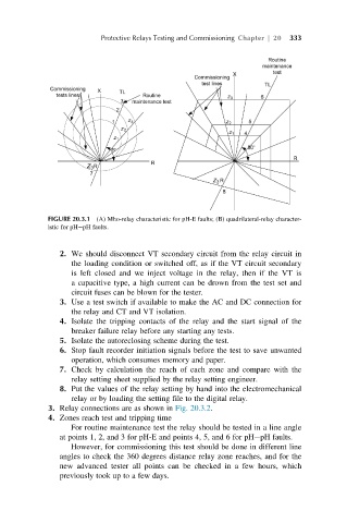
FIGURE 20.3.1 (A) Mho-relay characteristic for pH-E faults; (B) quadrilateral-relay character-
istic for pH pH faults.
2. We should disconnect VT secondary circuit from the relay circuit in
the loading condition or switched off, as if the VT circuit secondary
is left closed and we inject voltage in the relay, then if the VT is
a capacitive type, a high current can be drown from the test set and
circuit fuses can be blown for the tester.
3. Use a test switch if available to make the AC and DC connection for
the relay and CT and VT isolation.
4. Isolate the tripping contacts of the relay and the start signal of the
breaker failure relay before any starting any tests.
5. Isolate the autoreclosing scheme during the test.
6. Stop fault recorder initiation signals before the test to save unwanted
operation, which consumes memory and paper.
7. Check by calculation the reach of each zone and compare with the
relay setting sheet supplied by the relay setting engineer.
8. Put the values of the relay setting by hand into the electromechanical
relay or by loading the setting file to the digital relay.
3. Relay connections are as shown in Fig. 20.3.2.
4. Zones reach test and tripping time
For routine maintenance test the relay should be tested in a line angle
at points 1, 2, and 3 for pH-E and points 4, 5, and 6 for pH pH faults.
However, for commissioning this test should be done in different line
angles to check the 360 degrees distance relay zone reaches, and for the
new advanced tester all points can be checked in a few hours, which
previously took up to a few days.