
Page 342 - Practical Power System and Protective Relays Commissioning
P. 342
Protective Relays Testing and Commissioning Chapter | 20 337
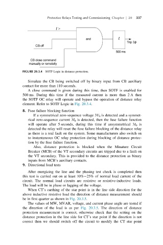
FIGURE 20.3.4 SOTF Logic in distance protection.
Simulate the CB being switched off by binary input from CB auxiliary
contact for more than 110 seconds.
A close command is given during this time, then SOTF is enabled for
500 ms. During this time if the measured current is more than 2 A then
the SOTF OC relay will operate and bypass the operation of distance relay
element. Refer to SOTF Logic in Fig. 20.3.4.
8. Fuse failure blocking function
If a symmetrical zero-sequence voltage 3V 0 is detected and a symmet-
rical zero-sequence current 3I 0 is detected, then the fuse failure function
will operate after 5 seconds, during this time if unsymmetrical 3I 0 is
detected the relay will reset the fuse failure blocking of the distance relay
as there is a real fault on the system. Some manufacturers also switch on
to instantaneous OC relay protection during blocking of distance protec-
tion by the fuse failure function.
Also, distance protection is blocked when the Minature Circuit
Breaker (MCB) of the VT secondary circuits are tripped due to a fault on
the VT secondary. This is provided to the distance protection as binary
inputs from MCB’s auxiliary contacts.
9. Directional load tests
After energizing the line and the phasing test check is completed then
this test is carried out on at least 10% 25% of normal load current of the
circuit. The normal load circuits are resistive or resistive-inductive loads.
The load will be in phase or lagging of the voltage.
When CT’s earthing of the star point is in the line side direction for the
above inductive resistive load the direction of distance measurement should
be in first quarter as shown in Fig. 20.3.5.
The values of MW, MVAR, voltage, and current phase angle are tested if
the direction of the load is as per Fig. 20.3.5. The direction of distance
protection measurement is correct, otherwise check that the setting on the
distance protection in the line side for CT’s star point if the direction is not
correct then we should switch off the circuit to modify the CT star point