
Page 347 - Practical Power System and Protective Relays Commissioning
P. 347
342 Practical Power System and Protective Relays Commissioning
4. Note that the supervision relay injects a DC voltage to monitor the pilot
cable condition.
5. This test should be done with the HV line switched off.
20.4.2 NEW TYPE LINE DIFFERENTIAL PROTECTION WITH
FIBER OPTIC LINK TESTING
1. Secondary injection tests
1.2 Pickup/drop off test
This test is done after we set the relay temporary in the loop back test
mode as the send optical signal (T X ) is forward to the receive (FO)-Fiber
Optic-port R x to simulate the operation of the commissioning channel and to
test the relay alone in one end only refer to Figs. 20.4.4 20.4.5).
FIGURE 20.4.4 Loop back simulation test.
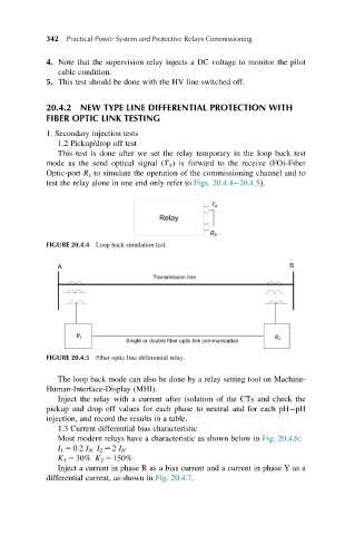
FIGURE 20.4.5 Fiber optic line differential relay.
The loop back mode can also be done by a relay setting tool on Machine-
Human-Interface-Display (MHI).
Inject the relay with a current after isolation of the CTs and check the
pickup and drop off values for each phase to neutral and for each pH pH
injection, and record the results in a table.
1.3 Current differential bias characteristic
Most modern relays have a characteristic as shown below in Fig. 20.4.6:
I 1 5 0.2 I N I 2 5 2 I N
K 1 5 30% K 2 5 150%
Inject a current in phase R as a bias current and a current in phase Y as a
differential current, as shown in Fig. 20.4.7.