
Page 352 - Practical Power System and Protective Relays Commissioning
P. 352
Protective Relays Testing and Commissioning Chapter | 20 347
TABLE 20.5.2 Test Sheet 1
Injected Injected Calculated Trip Measured Trip Error
Phase Current Time Time %
R 1.5 I diff
Y
B
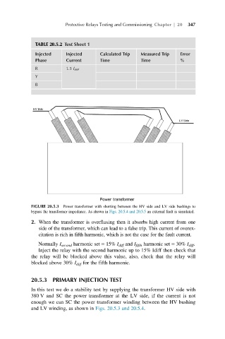
FIGURE 20.5.3 Power transformer with shorting between the HV side and LV side bushings to
bypass the transformer impedance. As shown in Figs. 20.5.4 and 20.5.5 an external fault is simulated.
2. When the transformer is overfluxing then it absorbs high current from one
side of the transformer, which can lead to a false trip. This current of overex-
citation is rich in fifth harmonic, which is not the case for the fault current.
Normally I second harmonic set 5 15% I diff and I fifth harmonic set 5 30% I diff .
Inject the relay with the second harmonic up to 15% Idiff then check that
the relay will be blocked above this value, also, check that the relay will
blocked above 30% I diff for the fifth harmonic.
20.5.3 PRIMARY INJECTION TEST
In this test we do a stability test by supplying the transformer HV side with
380 V and SC the power transformer at the LV side, if the current is not
enough we can SC the power transformer winding between the HV bushing
and LV winding, as shown in Figs. 20.5.3 and 20.5.4.