
Page 354 - Practical Power System and Protective Relays Commissioning
P. 354
Protective Relays Testing and Commissioning Chapter | 20 349
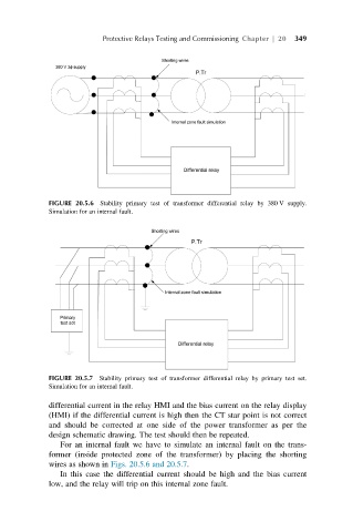
FIGURE 20.5.6 Stability primary test of transformer differential relay by 380 V supply.
Simulation for an internal fault.
FIGURE 20.5.7 Stability primary test of transformer differential relay by primary test set.
Simulation for an internal fault.
differential current in the relay HMI and the bias current on the relay display
(HMI) if the differential current is high then the CT star point is not correct
and should be corrected at one side of the power transformer as per the
design schematic drawing. The test should then be repeated.
For an internal fault we have to simulate an internal fault on the trans-
former (inside protected zone of the transformer) by placing the shorting
wires as shown in Figs. 20.5.6 and 20.5.7.
In this case the differential current should be high and the bias current
low, and the relay will trip on this internal zone fault.