
Page 356 - Practical Power System and Protective Relays Commissioning
P. 356
Protective Relays Testing and Commissioning Chapter | 20 351
A double busbars with a four-section system has one breaker per feeder.
Check that when D1 for feeder F1 and D3 of feeder F2 are connected to
section C, when we simulate a fault on section C with D13 and D14, CB7
are closed and CB1 and CB2 are also closed. This simulates the busbar
protection by secondary injection which will trip CB1, CB2, and C.B7. This
discrimination of the fault location is determined by busbar protection by the
bus isolator image (auxiliary contact from an isolator disconnector, such as
D1, which will inform the relay whether this disconnector is connected to
bus C or not.
By repeating the last procedures for a fault simulation on sections A B
and C D with all possible combination of disconnectors status open or
close, we can test the discrimination of the busbar protection—this means
that the busbar protection will trip only the section which has the fault and
leave the other three sections in service.
20.6.2 PRIMARY INJECTION STABILITY TEST
1. Ratio check for a reference circuit
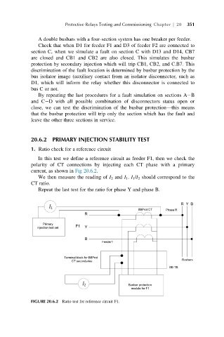
In this test we define a reference circuit as feeder F1, then we check the
polarity of CT connections by injecting each CT phase with a primary
current, as shown in Fig 20.6.2.
We then measure the reading of I 2 and I 1 . I 1 /I 2 should correspond to the
CT ratio.
Repeat the last test for the ratio for phase Y and phase B.
FIGURE 20.6.2 Ratio test for reference circuit F1.