
Page 351 - Practical Power System and Protective Relays Commissioning
P. 351
346 Practical Power System and Protective Relays Commissioning
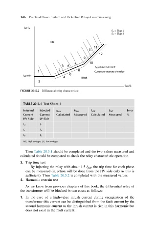
FIGURE 20.5.2 Differential relay characteristic.
TABLE 20.5.1 Test Sheet 1
Injected Injected I bias I bias I diff I diff Error
Current Current Calculated Measured Calculated Measured %
HV Side LV Side
I R I r
I Y I Y
I B I b
HV, high voltage; LV, low voltage.
Then Table 20.5.1 should be completed and the two values measured and
calculated should be compared to check the relay characteristic operation.
3. Trip time test
By injecting the relay with about 1.5 I diff , the trip time for each phase
can be measured (injection will be done from the HV side only as this is
sufficient). Then Table 20.5.2 is completed with the measured values.
4. Harmonic restrain test
As we know from previous chapters of this book, the differential relay of
the transformer will be blocked in two cases as follows:
1. In the case of a high-value inrush current during energization of the
transformer this current can be distinguished from the fault current by the
second harmonic current as the inrush current is rich in this harmonic but
does not exist in the fault current.