
Page 348 - Practical Power System and Protective Relays Commissioning
P. 348
Protective Relays Testing and Commissioning Chapter | 20 343
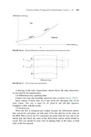
FIGURE 20.4.6 Biased differential protection characteristic for transmission lines.
FIGURE 20.4.7 Test of relay bias characteristic.
A drawing of the relay characteristic should follow the relay characteris-
tic provided by the manufacturer.
1.4 Differential relay operating time
Connect the relay and secondary injection tester as shown in Fig. 20.4.8.
Inject current of more than 0.2 A and check the operating time of the
relay repeat. This test is used for all phase-N and pH pH injection.
Complete a table with the results.
1.5 On-load test
When the line is energized and loaded, measure the differential current,
bias current for each phase on both ends of the line directly on the relay on
the MHI. Then reverse the CT connection star point from the line side to the
busbar side and check the value of the differential current which should be
raised. This test should be done with all tripping links of the relays at both
sides of the line opened.