
Page 344 - Practical Power System and Protective Relays Commissioning
P. 344
Protective Relays Testing and Commissioning Chapter | 20 339
Subchapter 20.4
Line Differential Protection Testing and
Commissioning
20.4.1 OLD-TYPE PILOT WIRE DIFFERENTIAL PROTECTION
TESTING
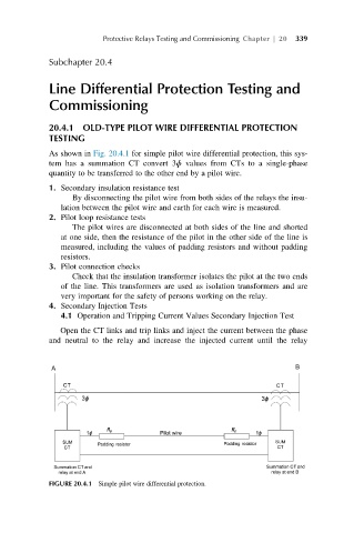
As shown in Fig. 20.4.1 for simple pilot wire differential protection, this sys-
tem has a summation CT convert 3ɸ values from CTs to a single-phase
quantity to be transferred to the other end by a pilot wire.
1. Secondary insulation resistance test
By disconnecting the pilot wire from both sides of the relays the insu-
lation between the pilot wire and earth for each wire is measured.
2. Pilot loop resistance tests
The pilot wires are disconnected at both sides of the line and shorted
at one side, then the resistance of the pilot in the other side of the line is
measured, including the values of padding resistors and without padding
resistors.
3. Pilot connection checks
Check that the insulation transformer isolates the pilot at the two ends
of the line. This transformers are used as isolation transformers and are
very important for the safety of persons working on the relay.
4. Secondary Injection Tests
4.1 Operation and Tripping Current Values Secondary Injection Test
Open the CT links and trip links and inject the current between the phase
and neutral to the relay and increase the injected current until the relay
FIGURE 20.4.1 Simple pilot wire differential protection.