
Page 349 - Practical Power System and Protective Relays Commissioning
P. 349
344 Practical Power System and Protective Relays Commissioning
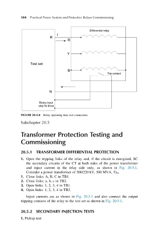
FIGURE 20.4.8 Relay operating time test connection.
Subchapter 20.5
Transformer Protection Testing and
Commissioning
20.5.1 TRANSFORMER DIFFERENTIAL PROTECTION
1. Open the tripping links of the relay and, if the circuit is energized, SC
the secondary circuits of the CT at both sides of the power transformer
and inject current in the relay side only, as shown in Fig. 20.5.1.
Consider a power transformer of 500/220 kV, 500 MVA, Yy 0 .
1. Close links: A, B, C in TB1.
2. Close links: a, b, c in TB2.
3. Open links: 1, 2, 3, 4 in TB1.
4. Open links: 1, 2, 3, 4 in TB2.
Inject currents are as shown in Fig. 20.5.1 and also connect the output
tripping contacts of the relay to the test set as shown in Fig. 20.5.1.
20.5.2 SECONDARY INJECTION TESTS
1. Pickup test