
Page 357 - Practical Power System and Protective Relays Commissioning
P. 357
352 Practical Power System and Protective Relays Commissioning
2. Phasing of the reference circuit CT
As in the ratio test we choose F1 (feeder 1) as a reference circuit, then
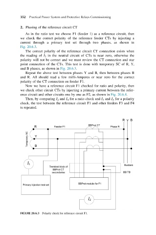
we check the correct polarity of the reference feeder CTs by injecting a
current through a primary test set through two phases, as shown in
Fig. 20.6.3.
The correct polarity of the reference circuit CT connection exists when
the reading of I 2 in the neutral circuit of CTs is near zero, otherwise the
polarity will not be correct and we must review the CT connection and star
point connection of the CTs. This test is done with temporary SC of R, Y,
and B phases, as shown in Fig. 20.6.3.
Repeat the above test between phases Y and B, then between phases B
and R. All should read a few milli-Amperes or near zero for the correct
polarity of the CT connection on feeder F1.
Now we have a reference circuit F1 checked for ratio and polarity, then
we check other circuit CTs by injecting a primary current between the refer-
ence circuit and other circuits one by one as F2, as shown in Fig. 20.6.4.
Then, by comparing I 2 and I 4 for a ratio check and I 3 and I 5 for a polarity
check, the test between the reference circuit F1 and other feeders F3 and F4
is repeated.
FIGURE 20.6.3 Polarity check for reference circuit F1.