
Page 362 - Practical Power System and Protective Relays Commissioning
P. 362
Protective Relays Testing and Commissioning Chapter | 20 357
20.7.2 SYNCHRONIZING RELAY TEST
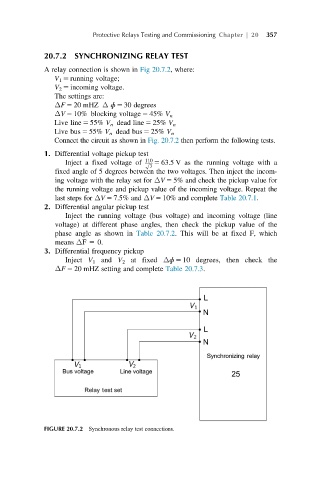
A relay connection is shown in Fig 20.7.2, where:
V 1 5 running voltage;
V 2 5 incoming voltage.
The settings are:
ΔF 5 20 mHZ Δ ɸ 5 30 degrees
ΔV 5 10% blocking voltage 5 45% V n
Live line 5 55% V n dead line 5 25% V n
Live bus 5 55% V n dead bus 5 25% V n
Connect the circuit as shown in Fig. 20.7.2 then perform the following tests.
1. Differential voltage pickup test
Inject a fixed voltage of 110 5 63.5 V as the running voltage with a
O3
fixed angle of 5 degrees between the two voltages. Then inject the incom-
ing voltage with the relay set for ΔV 5 5% and check the pickup value for
the running voltage and pickup value of the incoming voltage. Repeat the
last steps for ΔV 5 7.5% and ΔV 5 10% and complete Table 20.7.1.
2. Differential angular pickup test
Inject the running voltage (bus voltage) and incoming voltage (line
voltage) at different phase angles, then check the pickup value of the
phase angle as shown in Table 20.7.2. This will be at fixed F, which
means ΔF 5 0.
3. Differential frequency pickup
Inject V 1 and V 2 at fixed Δɸ 5 10 degrees, then check the
ΔF 5 20 mHZ setting and complete Table 20.7.3.
FIGURE 20.7.2 Synchronous relay test connections.