
Page 367 - Practical Power System and Protective Relays Commissioning
P. 367
362 Practical Power System and Protective Relays Commissioning
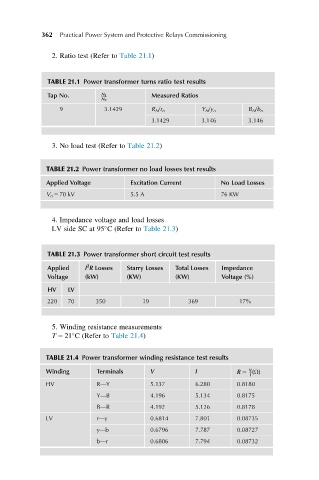
2. Ratio test (Refer to Table 21.1)
TABLE 21.1 Power transformer turns ratio test results
Tap No. N 1 Measured Ratios
N 2
9 3.1429 R N /r n Y N /y n B N /b n
3.1429 3.146 3.146
3. No load test (Refer to Table 21.2)
TABLE 21.2 Power transformer no load losses test results
Applied Voltage Excitation Current No Load Losses
V n 5 70 kV 5.5 A 76 KW
4. Impedance voltage and load losses
LV side SC at 95 C (Refer to Table 21.3)
TABLE 21.3 Power transformer short circuit test results
2
Applied I R Losses Starry Losses Total Losses Impedance
Voltage (kW) (KW) (KW) Voltage (%)
HV LV
220 70 350 19 369 17%
5. Winding resistance measurements
T 5 21 C (Refer to Table 21.4)
TABLE 21.4 Power transformer winding resistance test results
V
Winding Terminals V I R 5 (Ω)
I
HV R—Y 5.137 6.280 0.8180
Y—B 4.196 5.134 0.8175
B—R 4.192 5.126 0.8178
LV r—y 0.6814 7.801 0.08735
y—b 0.6796 7.787 0.08727
b—r 0.6806 7.794 0.08732