
Page 369 - Practical Power System and Protective Relays Commissioning
P. 369
Chapter 22
Final Substation Primary and
Energization and Loading Tests
22.1 FINAL PRIMARY INJECTION TEST OF SUBSTATION
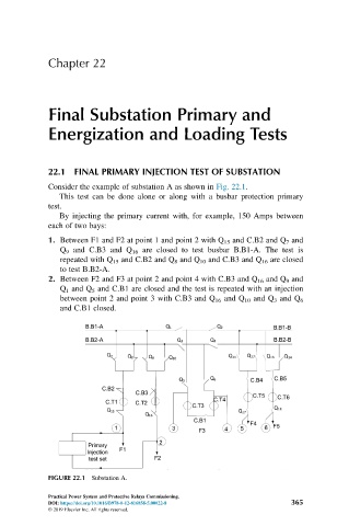
Consider the example of substation A as shown in Fig. 22.1.
This test can be done alone or along with a busbar protection primary
test.
By injecting the primary current with, for example, 150 Amps between
each of two bays:
1. Between F1 and F2 at point 1 and point 2 with Q 15 and C.B2 and Q 7 and
Q 9 and C.B3 and Q 16 are closed to test busbar B.B1-A. The test is
repeated with Q 15 and C.B2 and Q 8 and Q 10 and C.B3 and Q 16 are closed
to test B.B2-A.
2. Between F2 and F3 at point 2 and point 4 with C.B3 and Q 16 and Q 9 and
Q 1 and Q 5 and C.B1 are closed and the test is repeated with an injection
between point 2 and point 3 with C.B3 and Q 16 and Q 10 and Q 3 and Q 6
and C.B1 closed.
FIGURE 22.1 Substation A.
Practical Power System and Protective Relays Commissioning.
DOI: https://doi.org/10.1016/B978-0-12-816858-5.00022-8 365
© 2019 Elsevier Inc. All rights reserved.