
Page 69 - Practical Power System and Protective Relays Commissioning
P. 69
66 Practical Power System and Protective Relays Commissioning
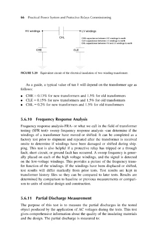
FIGURE 5.20 Equivalent circuit of the electrical insulation of two winding transformer.
As a guide, a typical value of tan δ will depend on the transformer age as
follows:
CHE 5 0.13% for new transformers and 1.5% for old transformers
CLE 5 0.15% for new transformers and 1.5% for old transformers
CHL 5 0.2% for new transformers and 1.5% for old transformers
5.6.10 Frequency Response Analysis
Frequency response analysis-FRA- or what we call in the field of transformer
testing (SFR test)- sweep frequency response analysis -can determine if the
windings of a transformer have moved or shifted. It can be completed as a
factory test prior to shipment and repeated after the transformer is received
onsite to determine if windings have been damaged or shifted during ship-
ping. This test is also helpful if a protective relay has tripped or a through
fault, short circuit, or ground fault has occurred. A sweep frequency is gener-
ally placed on each of the high voltage windings, and the signal is detected
on the low-voltage windings. This provides a picture of the frequency trans-
fer function of the windings. If the windings have been displaced or shifted,
test results will differ markedly from prior tests. Test results are kept in
transformer history files so they can be compared to later tests. Results are
determined by comparison to baseline or previous measurements or compari-
son to units of similar design and construction.
5.6.11 Partial Discharge Measurement
The purpose of this test is to measure the partial discharges in the tested
object produced by the application of AC voltages during the tests. This test
gives comprehensive information about the quality of the insulating materials
and the design. The partial discharge is measured to: