
Page 64 - Practical Power System and Protective Relays Commissioning
P. 64
Power Transformers Theory Testing and Commissioning Chapter | 5 61
FIGURE 5.15 Voltage ratio test of power transformer.
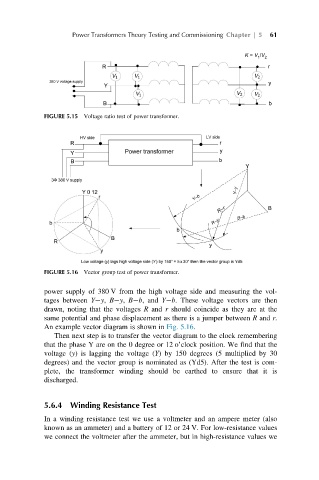
FIGURE 5.16 Vector group test of power transformer.
power supply of 380 V from the high voltage side and measuring the vol-
tages between Y y, B y, B b, and Y b. These voltage vectors are then
drawn, noting that the voltages R and r should coincide as they are at the
same potential and phase displacement as there is a jumper between R and r.
An example vector diagram is shown in Fig. 5.16.
Then next step is to transfer the vector diagram to the clock remembering
that the phase Y are on the 0 degree or 12 o’clock position. We find that the
voltage (y) is lagging the voltage (Y) by 150 degrees (5 multiplied by 30
degrees) and the vector group is nominated as (Yd5). After the test is com-
plete, the transformer winding should be earthed to ensure that it is
discharged.
5.6.4 Winding Resistance Test
In a winding resistance test we use a voltmeter and an ampere meter (also
known as an ammeter) and a battery of 12 or 24 V. For low-resistance values
we connect the voltmeter after the ammeter, but in high-resistance values we