
Page 63 - Practical Power System and Protective Relays Commissioning
P. 63
60 Practical Power System and Protective Relays Commissioning
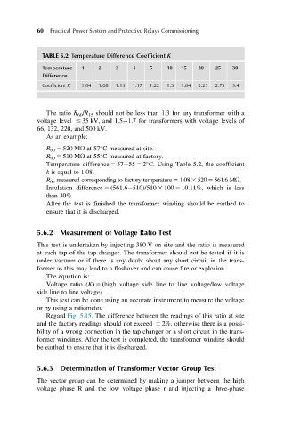
TABLE 5.2 Temperature Difference Coefficient K
Temperature 1 2 3 4 5 10 15 20 25 30
Difference
Coefficient K 1.04 1.08 1.13 1.17 1.22 1.5 1.84 2.25 2.75 3.4
The ratio R 60 /R 15 should not be less than 1.3 for any transformer with a
voltage level # 35 kV, and 1.5 1.7 for transformers with voltage levels of
66, 132, 220, and 500 kV.
As an example:
R 60 5 520 MΩ at 57 C measured at site.
R 60 5 510 MΩ at 55 C measured at factory.
Temperature difference 5 57 55 5 2 C. Using Table 5.2, the coefficient
k is equal to 1.08.
R 60 measured corresponding to factory temperature5 1.083 5205 561.6 MΩ.
Insulation difference 5 (561.6 510)/510 3 100 5 10.11%, which is less
than 30%
After the test is finished the transformer winding should be earthed to
ensure that it is discharged.
5.6.2 Measurement of Voltage Ratio Test
This test is undertaken by injecting 380 V on site and the ratio is measured
at each tap of the tap changer. The transformer should not be tested if it is
under vacuum or if there is any doubt about any short circuit in the trans-
former as this may lead to a flashover and can cause fire or explosion.
The equation is:
Voltage ratio (K) 5 (high voltage side line to line voltage/low voltage
side line to line voltage).
This test can be done using an accurate instrument to measure the voltage
or by using a ratiometer.
Regard Fig. 5.15. The difference between the readings of this ratio at site
and the factory readings should not exceed 6 2%, otherwise there is a possi-
bility of a wrong connection in the tap changer or a short circuit in the trans-
former windings. After the test is completed, the transformer winding should
be earthed to ensure that it is discharged.
5.6.3 Determination of Transformer Vector Group Test
The vector group can be determined by making a jumper between the high
voltage phase R and the low voltage phase r and injecting a three-phase