
Page 66 - Practical Power System and Protective Relays Commissioning
P. 66
Power Transformers Theory Testing and Commissioning Chapter | 5 63
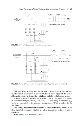
FIGURE 5.17 No-load current and power losses measurement.
FIGURE 5.18 Load losses, current measurement, and voltage impedance measurement.
The secondary winding low voltage side is short-circuited and the sec-
ondary current is circulated in the circuit. Power losses represent the total I 2
R losses in primary and secondary windings, and also include stray losses.
According to the Standards, the measured value of the losses is evaluated
at a reference temperature (e.g., at 75 C). The measuring temperature (t m )
losses are corrected to the reference temperature (75 C) according to the
Standards.
The voltage applied to the transformer to circulate the rated current in the
short-circuited secondary winding is called impedance voltage of power
transformer.
Refer to Fig. 5.18 for the test circuit.