
Page 68 - Practical Power System and Protective Relays Commissioning
P. 68
Power Transformers Theory Testing and Commissioning Chapter | 5 65
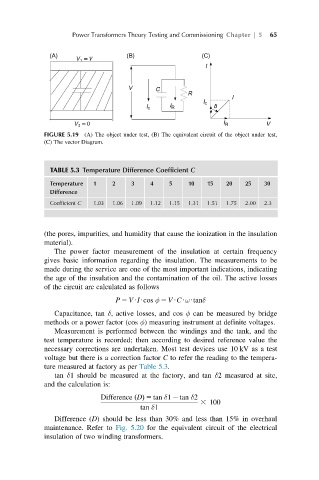
FIGURE 5.19 (A) The object under test, (B) The equivalent circuit of the object under test,
(C) The vector Diagram.
TABLE 5.3 Temperature Difference Coefficient C
Temperature 1 2 3 4 5 10 15 20 25 30
Difference
Coefficient C 1.03 1.06 1.09 1.12 1.15 1.31 1.51 1.75 2.00 2.3
(the pores, impurities, and humidity that cause the ionization in the insulation
material).
The power factor measurement of the insulation at certain frequency
gives basic information regarding the insulation. The measurements to be
made during the service are one of the most important indications, indicating
the age of the insulation and the contamination of the oil. The active losses
of the circuit are calculated as follows
P 5 VUIUcos φ 5 VUCUωUtanδ
Capacitance, tan δ, active losses, and cos φ can be measured by bridge
methods or a power factor (cos φ) measuring instrument at definite voltages.
Measurement is performed between the windings and the tank, and the
test temperature is recorded; then according to desired reference value the
necessary corrections are undertaken. Most test devices use 10 kV as a test
voltage but there is a correction factor C to refer the reading to the tempera-
ture measured at factory as per Table 5.3.
tan δ1 should be measured at the factory, and tan δ2 measured at site,
and the calculation is:
Difference DðÞ 5 tan δ1 2 tan δ2
3 100
tan δ1
Difference (D) should be less than 30% and less than 15% in overhaul
maintenance. Refer to Fig. 5.20 for the equivalent circuit of the electrical
insulation of two winding transformers.