
Page 55 - Principles and Applications of NanoMEMS Physics
P. 55
42 Chapter 2
2.2 Manifestation of Charge Discreteness
2.2.1 Effects of Charge Discreteness in Transmission Lines
The most fundamental element in circuits and systems is the interconnect
or transmission line (TL). TLs play an essential role in configuring circuits
and systems at all length scales [56]. Ideally, TLs are the medium through
which signals propagate, from one point to another, with no effect on the
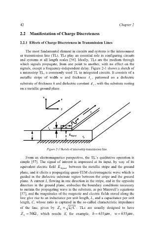
signals, except a frequency-independent delay. Figure 2-1 shows a sketch of
a microstrip TL, a commonly used TL in integrated circuits. It consists of a
metallic stripe of width w and thickness t , patterned on a dielectric
s
substrate of thickness h and dielectric constant ε , with the substrate resting
r
on a metallic ground plane.
x x
z z
y y
I I
t t t w w
s s s
E E
h h Signal ε ε ε
Signal
r r r
Figure 2-1 Sketch of microstrip transmission line.
From an electromagnetics perspective, the TL’s qualitative operation is
simple [57]. The signal of interest is impressed at its input, by way of its
equivalent electric field E between the metallic stripe and the ground
Signal
plane, and it elicits a propagating quasi-TEM electromagnetic wave which is
guided in the dielectric substrate region between the stripe and the ground
plane. A current I, flowing in one direction in the stripe, and in the opposite
direction in the ground plane, embodies the boundary conditions necessary
to sustain the propagating wave in the substrate, as per Maxwell’s equations
[57], and the magnitudes of the magnetic and electric fields stored along the
line give rise to an inductance per unit length, L, and a capacitance per unit
length, C, whose ratio is captured in the so-called characteristic impedance
of the line, given by Z = L C . TLs are usually designed to have
0
Z = 50 Ω , which results if, for example, h = 635 µ m , w = 635 µ m ,
0