
Page 113 - Principles of Applied Reservoir Simulation 2E
P. 113
98 Principles of Applied Reservoir Simulation
aspects of the reservoir modeling process can obscure the fundamental reservoir
concept in a model study. One way to integrate available data within the context
of a "big picture" is to apply the flow unit concept.
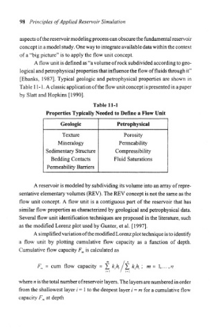
A flow unit is defined as "a volume of rock subdivided according to geo-
logical and petrophysical properties that influence the flow of fluids through it"
[Ebanks, 1987]. Typical geologic and petrophysical properties are shown in
Table 11 -1, A classic application of the flow unit concept is presented in a paper
by Slatt and Hopkins [1990],
Table 11-1
Properties Typically Needed to Define a Flow Unit
Geologic Petrophysical
Texture Porosity
Mineralogy Permeability
Sedimentary Structure Compressibility
Bedding Contacts Fluid Saturations
Permeability Barriers
A reservoir is modeled by subdividing its volume into an array of repre-
sentative elementary volumes (REV). The REV concept is not the same as the
flow unit concept. A flow unit is a contiguous part of the reservoir that has
similar flow properties as characterized by geological and petrophysical data.
Several flow unit identification techniques are proposed in the literature, such
as the modified Lorenz plot used by Gunter, et al. [1997].
A simplified variation of the modified Lorenz plot technique is to identify
a flow unit by plotting cumulative flow capacity as a function of depth.
is calculated as
Cumulative flow capacity F m
F m = cum flow capacity = ]£ k th. /£ k ih i ', m= \,,..,n
/= ! / /= !
where n is the total number of reservoir layers. The layers are numbered in order
from the shallowest layer / = 1 to the deepest layer i = m for a cumulative flow
capacity F m at depth