
Page 123 - Process Equipment and Plant Design Principles and Practices by Subhabrata Ray Gargi Das
P. 123
120 Chapter 5 Heat exchanger network analysis
There is a potential economic optimum from the balance of operating cost savings in utility reduction
and the effect of additional capital cost accrued.
(A) E2 (2kW) (B) E2 (2kW)
E5 (87kW)
E5 (87kW) CW
CW 96% Benzene
96% Benzene 87ºC 40ºC
87ºC 40ºC CW
CW
E1 (840kW) E6 (189kW) E1 (651kW)
Steam Steam
50% Benzene 50% Benzene
30ºC 90ºC 30ºC 70ºC 90ºC
E3 (8.7kW) E3 (8.7kW)
Steam Steam
E4 (189kW)
E4 (–)
30% Benzene
105ºC 40ºC 105ºC 30% Benzene
CW
40ºC
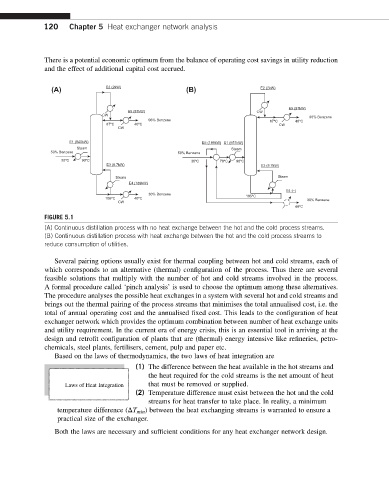
FIGURE 5.1
(A) Continuous distillation process with no heat exchange between the hot and the cold process streams.
(B) Continuous distillation process with heat exchange between the hot and the cold process streams to
reduce consumption of utilities.
Several pairing options usually exist for thermal coupling between hot and cold streams, each of
which corresponds to an alternative (thermal) configuration of the process. Thus there are several
feasible solutions that multiply with the number of hot and cold streams involved in the process.
A formal procedure called ‘pinch analysis’ is used to choose the optimum among these alternatives.
The procedure analyses the possible heat exchanges in a system with several hot and cold streams and
brings out the thermal pairing of the process streams that minimises the total annualised cost, i.e. the
total of annual operating cost and the annualised fixed cost. This leads to the configuration of heat
exchanger network which provides the optimum combination between number of heat exchange units
and utility requirement. In the current era of energy crisis, this is an essential tool in arriving at the
design and retrofit configuration of plants that are (thermal) energy intensive like refineries, petro-
chemicals, steel plants, fertilisers, cement, pulp and paper etc.
Based on the laws of thermodynamics, the two laws of heat integration are
(1) The difference between the heat available in the hot streams and
the heat required for the cold streams is the net amount of heat
Laws of Heat Integration that must be removed or supplied.
(2) Temperature difference must exist between the hot and the cold
streams for heat transfer to take place. In reality, a minimum
temperature difference (DT min ) between the heat exchanging streams is warranted to ensure a
practical size of the exchanger.
Both the laws are necessary and sufficient conditions for any heat exchanger network design.