
Page 131 - Process Equipment and Plant Design Principles and Practices by Subhabrata Ray Gargi Das
P. 131
128 Chapter 5 Heat exchanger network analysis
can be 1e2 C for plate fin designs. It is important to note that such constraints apply only to ex-
changers operating around the pinch point. Additional constraints apply if vaporisation or conden-
sation is occurring at the point of closest approach.
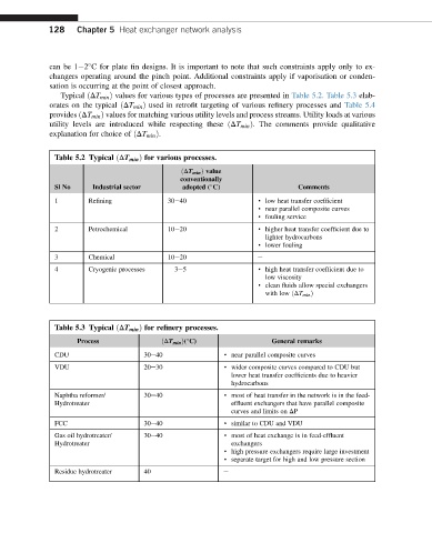
Typical ðDT min Þ values for various types of processes are presented in Table 5.2. Table 5.3 elab-
orates on the typical ðDT min Þ used in retrofit targeting of various refinery processes and Table 5.4
provides ðDT min Þ values for matching various utility levels and process streams. Utility loads at various
utility levels are introduced while respecting these ðDT min Þ. The comments provide qualitative
explanation for choice of ðDT min Þ.
Table 5.2 Typical ðDT min Þ for various processes.
ðDT min Þ value
conventionally
Sl No Industrial sector adopted ( C) Comments
1 Refining 30e40 · low heat transfer coefficient
· near parallel composite curves
· fouling service
2 Petrochemical 10e20 · higher heat transfer coefficient due to
lighter hydrocarbons
· lower fouling
3 Chemical 10e20 e
4 Cryogenic processes 3e5 · high heat transfer coefficient due to
low viscosity
· clean fluids allow special exchangers
with low ðDT min Þ
Table 5.3 Typical ðDT min Þ for refinery processes.
Process ðDT min Þ( C) General remarks
CDU 30e40 · near parallel composite curves
VDU 20e30 · wider composite curves compared to CDU but
lower heat transfer coefficients due to heavier
hydrocarbons
Naphtha reformer/ 30e40 · most of heat transfer in the network is in the feed-
Hydrotreater effluent exchangers that have parallel composite
curves and limits on DP
FCC 30e40 · similar to CDU and VDU
Gas oil hydrotreater/ 30e40 · most of heat exchange is in feed-effluent
Hydrotreater exchangers
· high pressure exchangers require large investment
· separate target for high and low pressure section
Residue hydrotreater 40 e