
Page 15 - Process Equipment and Plant Design Principles and Practices by Subhabrata Ray Gargi Das
P. 15
1.3 The design process 9
to the technically optimized design coinciding with the optimum economic design. An example of this
is a furnace design that has maximum efficiency within the available funding limitation/constraint(s).
Maximizing furnace efficiency by design reduces fuel cost, which is the dominant component of
operating expense.
Another example of optimized design can be the selection of pipeline size and pump. The smaller
size of pipe requires lower capital investment but increases the line pressure drop. This would require
the pump to develop a high head. A pump with a higher delivery head would, not only cost more but
would also increase the power consumption. This calls for optimizing the pipeline size and the pump
together as a system.
In case of arriving at optimum design of equipment, the overall economic parameter, for example,
annualized total cost comprising of its component contributions from capital investment and operating
cost, is the objective function to be minimized. This is illustrated later in the book while dealing with
optimum design of distillation column.
One may note that multiple optima are also possible in the case of large design problems, for
example, the configuration of large process plants like refinery or fertilizers. This means there can be
more than one combination of capacities of plants in a refinery complex being optimally designed for
maximizing profit.
Design steps
Equipment design is usually a two-stage process. In the first step, the optimum design is arrived at
through an optimization procedure either by solving a rigorous mathematical problem or by using a
graphical procedure. This design is detailed in the next step. An example of this is illustrated in
Chapter 11.
Detailed design of the equipment is carried out by referring to the appropriate “Design Codes and
Standards” for design, materials, and inspection. Relevant codes for the design of specific equipment
are discussed in the corresponding chapters and a list of some relevant codes used in the design of
process equipment is presented in the Appendix section.
1.3.1 Deliverables
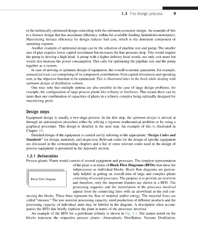
Process plants: Plants would consist of several equipment and processes. The simplest representation
of the plant is in terms of Block Flow Diagrams (BFDs) that show the
subprocesses as individual blocks. Block flow diagrams are particu-
larly helpful in getting an overall idea of large and complex plants
Block Flow Diagram consisting of several processes. The purpose is to provide an overview
and therefore, only the important features are shown in a BFD. The
processing sequence and the interrelation of the processes involved
appear from the connecting lines with an arrowhead at the end con-
necting the blocks. These lines represent the flow of material and/or energy. The material flows are
called “streams.” The raw material processing capacity, rated production of different products and the
processing capacity of individual units may be labeled in the diagram. A description often accom-
panies the BFD that briefly explains the plant in terms of the processes involved.
An example of the BFD for a petroleum refinery is shown in Fig. 1.1. The names noted on the
blocks represent the respective process plantsdAtmospheric Distillation, Vacuum Distillation,