
Page 20 - Process Equipment and Plant Design Principles and Practices by Subhabrata Ray Gargi Das
P. 20
14 Chapter 1 General aspects of process design
Ø298 202 34
Ø345
3
25
Ø6mmX185 nos
DETAIL-D
36
3 43
DEAIL-C
M24X3 15.4
15
DETAIL-B
15 3 122
N31 45.6 158.5 3
134.5 3
DETAIL-A 75
73.2 134.5 DETAIL-C N32 8
DETAIL-D M24X3 DETAIL-A
28.3 28.3
DETAIL-B
NOTE :
1. N31 & N32-- 1/2**NB, SCH40 NOZZLE with 1/2*NB Flange as per*ASA Class 150/B16.5/BS 1560
2. All bolts are M24X3, 50 mm Lg. as per ANSI B18.2.3.5M-1979
3. All Nuts are M24X3 as per ANSI B18.2.4.1M & M24 regular washer asper ANSIB 18.22M-1981
4. M.O.C. of all equipments, Vessles, Flanges, Pipes, Nozzles, Nut & Bolts IsSS304
DRAIN POT
FIGURE 1.4
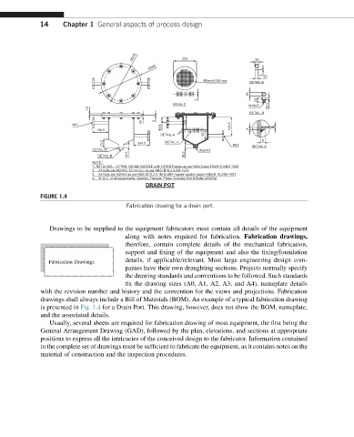
Fabrication drawing for a drain port.
Drawings to be supplied to the equipment fabricators must contain all details of the equipment
along with notes required for fabrication. Fabrication drawings,
therefore, contain complete details of the mechanical fabrication,
support and fixing of the equipment and also the fixing/foundation
Fabrication Drawings details, if applicable/relevant. Most large engineering design com-
panies have their own draughting sections. Projects normally specify
the drawing standards and conventions to be followed. Such standards
fix the drawing sizes (A0, A1, A2, A3, and A4), nameplate details
with the revision number and history and the convention for the views and projections. Fabrication
drawings shall always include a Bill of Materials (BOM). An example of a typical fabrication drawing
is presented in Fig. 1.4 for a Drain Port. This drawing, however, does not show the BOM, nameplate,
and the associated details.
Usually, several sheets are required for fabrication drawing of most equipment, the first being the
General Arrangement Drawing (GAD), followed by the plan, elevations, and sections at appropriate
positions to express all the intricacies of the conceived design to the fabricator. Information contained
in the complete set of drawings must be sufficient to fabricate the equipment, as it contains notes on the
material of construction and the inspection procedures.