
Page 17 - Process Equipment and Plant Design Principles and Practices by Subhabrata Ray Gargi Das
P. 17
1.3 The design process 11
minimum, normal, and maximum throughput. Each stream is uniquely numbered, usually within a
circle or a rotated square. Equipment symbols are more or less industry standard, with minor variation
from one engineering company to another.
It normally includes:
• Process scheme with streamsdconventionally the flow is from left to right
• Major equipment symbols, names and identification numbers
• Control valves and valves that affect the operation of the system; this is not mandatory
• Interconnection with other systems
• Major bypass and recirculation lines
• System ratings and operational values as minimum, normal and maximum flow, temperature, and
pressure
• Composition of streams
The stream details are provided on the PFD sheets as a stream table. The information provided by
stream tables includes
(i) stream flow rate
(ii) flow rates and composition of the stream components
(iii) temperature and pressure
(iv) phases flowing (liquid, solid, vapor or combinations of these)
(v) enthalpy
To Tail gas Water
sheet no 3
10 11
2
Air
CW
Filter 8
Compressor 2A Absorbor
1A 3 Steam
5 Cooler
Ammonia 1 6 9
4
From Filter CW
sheet no 3 Vaporiser Reactor W.H.B. 7 12
(Oxidiser) Condenser Mixer
13
Product
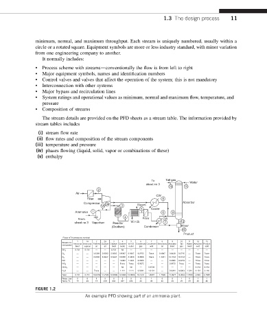
FIGURE 1.2
An example PFD showing part of an ammonia plant.