
Page 16 - Process Equipment and Plant Design Principles and Practices by Subhabrata Ray Gargi Das
P. 16
10 Chapter 1 General aspects of process design
Fuel Gas
Amine Treating Refinery Fuel
H S
Other Gases 2 Claus Sulfur Sulfur
Plant
LPG
Gas Gas Processing Merox Treaters H S from
2
Sour Water Stripper
Gas H 2 Gas H 2
Light Isomerization Isomerate
Hydrotreater
Naphtha Plant
Gas H Gas H 2
2
Heavy Hydrotreater Reformer Reformate
Catalytic
Atmospheric Distillation Merox Treater Kerosene
Naphtha
Crude Kerosene Gas H 2
Oil Gas H 2 Hydrocracker Gasoline
Diesel Oil
Hydrotreater Diesel Oil Hydrocracker Diesel Oil Gas Gasoline Blending Pool
Atmospheric i-Butane
Alkylate
Gas Oil Butenes Alkylation
Heavy Vacuum
Pentenes
Gas Oil Gas Gas H 2
Evacuated
non-condensibles Gas H 2 Naphtha Hydrotreater FCC Gasoline
Atmospheric Bottoms Light Hydrotreater Fluid Catalytic Cracker (FCC) FCC Gas oil
FCC Feed
Vacuum
Gas Oil Fuel oil
Vacuum Distillation Vacuum
Heavy
Gas Oil
Asphalt
Air Blowing Asphalt
FIGURE 1.1
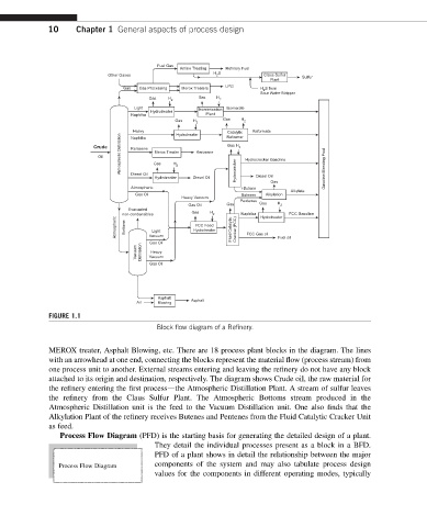
Block flow diagram of a Refinery.
MEROX treater, Asphalt Blowing, etc. There are 18 process plant blocks in the diagram. The lines
with an arrowhead at one end, connecting the blocks represent the material flow (process stream) from
one process unit to another. External streams entering and leaving the refinery do not have any block
attached to its origin and destination, respectively. The diagram shows Crude oil, the raw material for
the refinery entering the first processdthe Atmospheric Distillation Plant. A stream of sulfur leaves
the refinery from the Claus Sulfur Plant. The Atmospheric Bottoms stream produced in the
Atmospheric Distillation unit is the feed to the Vacuum Distillation unit. One also finds that the
Alkylation Plant of the refinery receives Butenes and Pentenes from the Fluid Catalytic Cracker Unit
as feed.
Process Flow Diagram (PFD) is the starting basis for generating the detailed design of a plant.
They detail the individual processes present as a block in a BFD.
PFD of a plant shows in detail the relationship between the major
Process Flow Diagram components of the system and may also tabulate process design
values for the components in different operating modes, typically