
Page 19 - Process Equipment and Plant Design Principles and Practices by Subhabrata Ray Gargi Das
P. 19
1.3 The design process 13
(A) IAS
(Instrument Air Supply)
11FT
FV-3-3040 10
From Transfer Pump Mixer To Reactor
11 P-201 11 M-08 11 R-102
IAS S
(Instrument Air Supply)
Sample Point
11FT
FV-3-3041 11
From Transfer Pump
11 P-204
(B) SM
11 L 11
N4 N5
SOLVENT N1 N2
FROM UNIT 1
11-100-PE-N
11 T 01 PA: 6 basg
M1
11 L 12 11 P1 13
N6
AL N3 M
100/50 50/100
SOLVENT
TO UNIT 3
11-100-PE-N
11 P 01
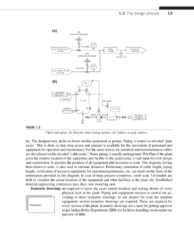
FIGURE 1.3
P&ID examples: (A) Reactor feed mixing system, (B) Solvent supply system.
etc. The designer may prefer to locate similar equipment in groups. Piping is routed on elevated “pipe
racks.” This is done so that clear access and passage is available for the movement of personnel and
equipment for operation and maintenance. For the same reason, the electrical and instrumentation cables
are also placed on the elevated “cable racks.” Water piping is usually underground. Plot Plan of the plant
gives the relative location of the equipment and facility in the scaled plan, a vital input for civil design
and construction. It specifies the position of all equipment and structures to scale. This diagram, having
been drawn to scale, is also used to estimate distances. Preliminary estimation of cable length, piping
length, verification of access to equipment for operation/maintenance, etc. are made on the basis of the
information provided in this diagram. In case of large process complexes, small scale 3-d models are
built to visualize the actual location of the equipment and other facilities at the plant site. Established
detailed engineering contractors have their own modeling unit.
Isometric drawings are required to know the exact spatial location and routing details of every
physical item in the plant. Piping and equipment erection is carried out ac-
cording to these isometric drawings. In any project for even the simplest
equipment, several isometric drawings are required. These are required for
Isometric every section of the plant. Isometric drawings are a must for getting approval
as per Indian Boiler Regulations (IBR) for facilities handling steam under the
purview of IBR.