
Page 25 - Process Equipment and Plant Design Principles and Practices by Subhabrata Ray Gargi Das
P. 25
2.2 Exchanger types 21
and there is no mixing of fluids. Tubular, plate-type and extended surface exchangers are
recuperators.
Tubular heat exchangers are usually the shell and tube, double pipe or spiral tube type. These
have considerable flexibility in design by changing the tube diameter, length and arrangement. They
can be designed for high pressure relative to the environment and high pressure difference between the
fluids. They are the most common type of heat exchanger both for systems without and with phase
change. These are not efficient for gasegas heat exchange but can be used when the pressure is very
high or fouling is a severe problem for at least one of the fluids and no other exchanger will work.
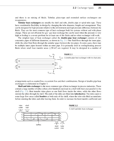
The simplest type of heat exchanger called the double-pipe heat exchanger consists of two
concentric pipes of different diameters, as shown in Fig. 2.1. One fluid flows through the inner pipe,
while the other fluid flows through the annular space between the two pipes. In some cases, there may
be multiple inner pipes housed within an outer pipe. It is primarily used in cooling/heating process
2
fluids where small heat transfer areas ( 50 m ) are required. It may be designed in a number of
m h FIGURE 2.1
T h,in
T c,out A double-pipe heat exchanger with two hair pins.
m c
T c,in
m c
T h,out m h
arrangements such as counterflow, co-current flow and their combinations. Design of double-pipe heat
exchangers is elaborated in Chapter 3.
Shell and tube exchanger is the most common type of heat exchanger in process industries. These
contain a large number of tubes (often a few hundred) enclosed in a shell with their axes parallel to the
shell (Fig. 2.2). Heat transfer takes place as one fluid flows inside the tubes, while the other flows
outside the tubes through the shell. The ends of the tubes are fitted into tubesheet(s). The tubes open to
some large flow areas called headers at both ends of the shell, where the tube-side fluid accumulates
before entering the tubes and after leaving them. In order to increase the heat transfer coefficient and
tube shell FIGURE 2.2
outlet inlet
A shell and tube heat exchanger.
baffles
shell tube
outlet inlet