
Page 26 - Process Equipment and Plant Design Principles and Practices by Subhabrata Ray Gargi Das
P. 26
22 Chapter 2 Heat transfer processes in industrial scale
obtain a more compact exchanger for the same heat duty, the shell- and the tube-side fluids are often
made to undergo several changes in flow direction (passes). Multipassing on the tube side is achieved
by dividing the headers with partition plates (pass partition plates). Baffles are generally fitted over
the tube bundle to force the shell-side fluid to flow across the shell to enhance heat transfer, support the
tubes and maintain uniform spacing between them. The assembly of baffles and tubes are held together
by tie rods and spacers. Many variations of this basic type are available e the differences being
mainly in the detailed features of construction and provisions for differential thermal expansion
between the tubes and the shell. These are elaborated in Chapter 4. Typical S&T exchangers
2
3
accommodate 50e100 m heat transfer area per m of equipment volume. Use of extended heat
transfer surfaces (fins/studs) is also possible in these exchangers.
Spiral-type exchangers consist of one or more spirally wound tubular coils fitted in a shell. The
heat transfer rate is higher as compared to a straight tube and for a given duty, the pressure drop is
usually lower than for an equivalent shell and tube exchanger. Spiralling provides high amount of heat
transfer surface in a given volume of the shell. Thermal expansion is not a problem with these
exchangers but mechanical cleaning is almost impossible. In another variation, the construction is
similar to the wound membrane modules used for separation.
Plate heat exchangers (PHEs) are highly compact and have recently gained high popularity. The
hot and cold fluids flow through alternate passages separated by thin plates assembled together. They
can pack about three times heat transfer area per unit equipment volume as compared to S&T
exchangers. Plate-type exchangers are rectangular metal plates held together in a frame, sealed around
the edges by gaskets. The frame usually has a fixed end cover fitted with connecting ports and a
movable end cover. An upper and a lower carrying bar guide the plates and ensure proper alignment.
These plates may be made either by stamping or embossing sheet metal to provide narrow, tortuous
flow passages. This generates severe turbulence, provides high heat transfer coefficient and decreases
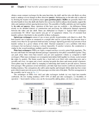
fouling tendency. The corrugations also add to plate rigidity and strength. Either plate has four corner
ports which in pairs provide access to flow passages on either side of the plate. The flow arrangement in
the assembly can be seen in Fig. 2.3.
The advantages of PHEs over shell and tube exchangers include (a) very high heat transfer
coefficient, (b) low fouling tendency (10%e25% of shell and tube exchanger), (c) flexibility of
operation e heat transfer surface area can be increased by adding plates, (d) more compact and less
SINGLE-PASS ARRANGEMENT MULTI-PASS ARRANGEMENT
Fixed End Movable End
Fixed End Movable End
Hot In
Cold Out
Cold In
Cold Out Cold In
Hot Out
Hot In Hot Out
123456 78
12 3 4 5 6 7 8
FIGURE 2.3
Flow arrangement in a plate-type exchanger.