
Page 29 - Process Equipment and Plant Design Principles and Practices by Subhabrata Ray Gargi Das
P. 29
2.2 Exchanger types 25
fluid when it flows through the matrix. Hence, the heat transfer is not unidirectional as in recuperators.
To operate with continuous flow of streams and limit the periodic temperature variation of the fluids,
either the matrix is physically moved periodically into and out of the fixed stream of gases (rotary
regenerator) or the gas flow is diverted using valves to and from the fixed matrices (fixed matrix
regenerator). A small amount of fluid is always trapped in the matrix that gets mixed with the other
fluid stream on switching of the fluids. Also a small leakage of the higher pressure fluid to the lower
pressure fluid is expected in real systems. Therefore, it cannot be used for systems where contami-
nation of one fluid by the other is unacceptable. In air heating applications, humid air may transfer
moisture up to about 5% to dry air. The advantages of regenerators over recuperators are
(a) compactness e smaller exchanger for given exchanger effectiveness and pressure drop, (b) cheaper
option, (c) simpler inlet and outlet header design for distribution of gases in the matrix and (d) can
work even with particulate laden gases that cause fouling in recuperators.
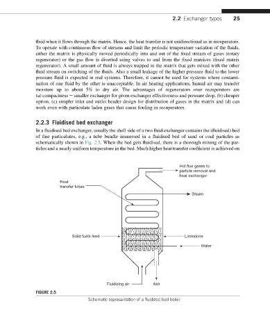
2.2.3 Fluidised bed exchanger
In a fluidised bed exchanger, usually the shell side of a two fluid exchanger contains the (fluidised) bed
of fine particulates, e.g., a tube bundle immersed in a fluidised bed of sand or coal particles as
schematically shown in Fig. 2.5. When the bed gets fluidised, there is a thorough mixing of the par-
ticles and a nearly uniform temperature in the bed. Much higher heat transfer coefficient is achieved on
Hot flue gases to
particle removal and
heat exchanger
Heat
transfer tubes
Steam
Solid fuels feed Limestone
Water
Fluidizing air Ash
FIGURE 2.5
Schematic representation of a fluidized bed boiler.