
Page 31 - Process Equipment and Plant Design Principles and Practices by Subhabrata Ray Gargi Das
P. 31
2.3 Flow arrangement 27
1 1 1
2 2
2
(A) (B) (C)
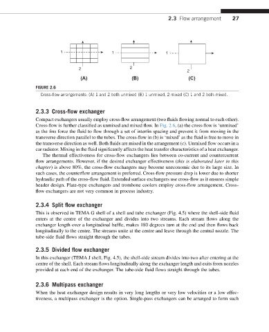
FIGURE 2.6
Cross-flow arrangements: (A) 1 and 2 both unmixed (B) 1 unmixed, 2 mixed (C) 1 and 2 both mixed.
2.3.3 Cross-flow exchanger
Compact exchangers usually employ cross-flow arrangement (two fluids flowing normal to each other).
Cross-flow is further classified as unmixed and mixed flow. In Fig. 2.6, (a) the cross-flow is ‘unmixed’
as the fins force the fluid to flow through a set of interfin spacing and prevent it from moving in the
transverse direction parallel to the tubes. The cross-flow in (b) is ‘mixed’ as the fluid is free to move in
the transverse direction as well. Both fluids are mixed in the arrangement (c). Unmixed flow occurs in a
car radiator. Mixing in the fluid significantly affects the heat transfer characteristics of a heat exchanger.
The thermal effectiveness for cross-flow exchangers lies between co-current and countercurrent
flow arrangements. However, if the desired exchanger effectiveness (this is elaborated later in this
chapter) is above 80%, the cross-flow exchangers may become uneconomic due to its large size. In
such cases, the counterflow arrangement is preferred. Cross-flow pressure drop is lower due to shorter
hydraulic path of the cross-flow fluid. Extended surface exchangers use cross-flow as it ensures simple
header design. Plate-type exchangers and trombone coolers employ cross-flow arrangement. Cross-
flow exchangers are not very common in process industry.
2.3.4 Split flow exchanger
This is observed in TEMA G shell of a shell and tube exchanger (Fig. 4.5) where the shell-side fluid
enters at the centre of the exchanger and divides into two streams. Each stream flows along the
exchanger length over a longitudinal baffle, makes 180 degrees turn at the end and then flows back
longitudinally to the centre. The streams unite at the centre and leave through the central nozzle. The
tube-side fluid flows straight through the tubes.
2.3.5 Divided flow exchanger
In this exchanger (TEMA J shell, Fig. 4.5), the shell-side stream divides into two after entering at the
centre of the shell. Each stream flows longitudinally along the exchanger length and exits from nozzles
provided at each end of the exchanger. The tube-side fluid flows straight through the tubes.
2.3.6 Multipass exchanger
When the heat exchanger design results in very long lengths or very low velocities or a low effec-
tiveness, a multipass exchanger is the option. Single-pass exchangers can be arranged to form such