
Page 28 - Process Equipment and Plant Design Principles and Practices by Subhabrata Ray Gargi Das
P. 28
24 Chapter 2 Heat transfer processes in industrial scale
channel
heat pipe
fin
Hot fluid channel Cold fluid
channel
Separator
plate
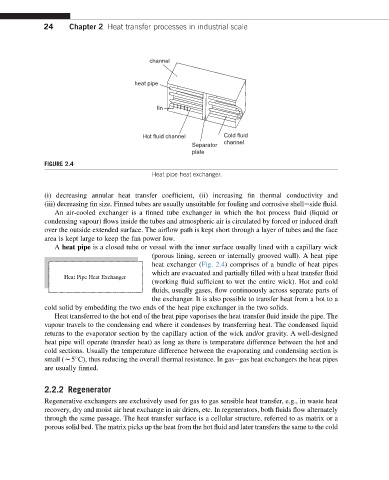
FIGURE 2.4
Heat pipe heat exchanger.
(i) decreasing annular heat transfer coefficient, (ii) increasing fin thermal conductivity and
(iii) decreasing fin size. Finned tubes are usually unsuitable for fouling and corrosive shelleside fluid.
An air-cooled exchanger is a finned tube exchanger in which the hot process fluid (liquid or
condensing vapour) flows inside the tubes and atmospheric air is circulated by forced or induced draft
over the outside extended surface. The airflow path is kept short through a layer of tubes and the face
area is kept large to keep the fan power low.
A heat pipe is a closed tube or vessel with the inner surface usually lined with a capillary wick
(porous lining, screen or internally grooved wall). A heat pipe
heat exchanger (Fig. 2.4) comprises of a bundle of heat pipes
which are evacuated and partially filled with a heat transfer fluid
Heat Pipe Heat Exchanger
(working fluid sufficient to wet the entire wick). Hot and cold
fluids, usually gases, flow continuously across separate parts of
the exchanger. It is also possible to transfer heat from a hot to a
cold solid by embedding the two ends of the heat pipe exchanger in the two solids.
Heat transferred to the hot end of the heat pipe vaporises the heat transfer fluid inside the pipe. The
vapour travels to the condensing end where it condenses by transferring heat. The condensed liquid
returns to the evaporator section by the capillary action of the wick and/or gravity. A well-designed
heat pipe will operate (transfer heat) as long as there is temperature difference between the hot and
cold sections. Usually the temperature difference between the evaporating and condensing section is
small (w5 C), thus reducing the overall thermal resistance. In gasegas heat exchangers the heat pipes
are usually finned.
2.2.2 Regenerator
Regenerative exchangers are exclusively used for gas to gas sensible heat transfer, e.g., in waste heat
recovery, dry and moist air heat exchange in air driers, etc. In regenerators, both fluids flow alternately
through the same passage. The heat transfer surface is a cellular structure, referred to as matrix or a
porous solid bed. The matrix picks up the heat from the hot fluid and later transfers the same to the cold