
Page 32 - Process Equipment and Plant Design Principles and Practices by Subhabrata Ray Gargi Das
P. 32
28 Chapter 2 Heat transfer processes in industrial scale
Shell fluid
Tube
CONDENSING T h,in fluid
T h,in T h,out
COOLING
T c,out T h,out
T s
HEATING
T c,in T c,out T c,in
EVAPORATING
T
a) BOTH FLUIDS CHANGING e) COUNTERFLOW , NO PHASE t
PHASE CHANGE
T h,in CONDENSING T h,out DE-SUPERHEATING T t
SUBCOOLING
(B)
T h,in CONDENSING
T c,out
HEATING T c,out Shell fluid
T c,in HEATING T c,in
b) ONE FLUID CHANGING f) ONE FLUID CHANGING
PHASE PHASE
Tube
fluid
T h,in T h,in
COOLING COOLING
T c,out
T h,out
T h,out
EVAPORATING
HEATING
EVAPORATING SUPERHEATING
T c,in T c,out
c) ONE FLUID CHANGING
PHASE ONE FLUID CHANGING T
PHASE s
T h,in PARTIAL
COOLING
T h,in CONDENSATION
T h,out
T c,out
T h,out
T c,out
HEATING
T c,in HEATING T c,in
T t
d) PARALLEL FLOW , NO CONDENSABLE AND
PHASE CHANGE NON-CONDENSABLE
COMPONENTS
(A) (C)
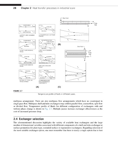
FIGURE 2.7
Temperature profile of fluids in different cases.
multipass arrangement. There are also multipass flow arrangements which have no counterpart in
single-pass flow. Multipass shell and tube exchangers may exhibit parallel flow, counterflow, split flow
or divided flow. Temperature profile of fluids for different configuration of exchangers with and
without phase change is shown in Fig. 2.7. Multiple passes increase exchanger effectiveness at the
cost of increased pressure drop.
2.4 Exchanger selection
The aforementioned discussion highlights the variety of available heat exchangers and the large
number of dimensional variables associated with different components of a shell and tube exchanger or
surface geometries for plate-type, extended surface or regenerative exchangers. Regarding selection of
the most suitable exchanger option, one must remember that there is rarely a single option that is best