
Page 160 - Process Modelling and Simulation With Finite Element Methods
P. 160
Extended Multiphysics 147
of stabilizing the system since the throughput U is greater than unity (the no
recycle throughput), but a purge may be necessary to avoid an infinite
recycle ratio due to build up of reactants or trace impurities. It is always good
chemical engineering design practice to include a purge, and then minimize it in
operation.
Implementing the Changes for Recycle
In principle, it should not be difficult to add a second weak subdomain mode for
the buffer tank. In practice, it was rather frustrating, as I unearthed an apparent
bug in the convectioddiffusion application mode that took some ingenuity to
create a workaround. Before finding the bug and workaround, however, I set up
the FEMLAB model with several variations. This exercise turned out to be a
tour de force in coupling variables.
The strategy is simply to create a O-D domain (as we have done many times
before) to implement the ODE in time (4.6) and appropriate couplings to import
the reactor outlet concentrations and merge the recycle with the feed stream into
the reactor inlet.
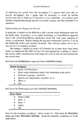
Pull down the Multiphysics menu and Select Add/Edit modes.
Select 1-D dimension
Select weak subdomain mode, time dependent weak solver
0
Element: Lagrange - quadratic
Specify two independent variables: uc vc
0 More>>
OK
Pull down the Draw menu and select Specify Geometry.
Draw Mode
Name: buffer
Start: -2
stop: -1
Apply
0 OK
Now for the boundary conditions. Select mode wl. Pull down the Boundary
menu and select Boundary Settings. Setup the boundary conditions as in the
table below.