
Page 158 - Process Modelling and Simulation With Finite Element Methods
P. 158
Extended Multiphysics 145
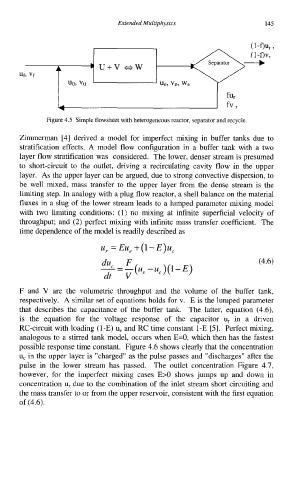
Figure 4.5 Simple flowsheet with heterogeneous reactor, separator and recycle.
Zimmerman [4] derived a model for imperfect mixing in buffer tanks due to
stratification effects. A model flow configuration in a buffer tank with a two
layer flow stratification was considered. The lower, denser stream is presumed
to short-circuit to the outlet, driving a recirculating cavity flow in the upper
layer. As the upper layer can be argued, due to strong convective dispersion, to
be well mixed, mass transfer to the upper layer from the dense stream is the
limiting step. In analogy with a plug flow reactor, a shell balance on the material
fluxes in a slug of the lower stream leads to a lumped parameter mixing model
with two limiting conditions: (1) no mixing at infinite superficial velocity of
throughput; and (2) perfect mixing with infinite mass transfer coefficient. The
time dependence of the model is readily described as
U, Eu, +(l-E)uc
du
--=-(ue F -uc)(l-E) (4.6)
dt V
F and V are the volumetric throughput and the volume of the buffer tank,
respectively. A similar set of equations holds for v. E is the lumped parameter
that describes the capacitance of the buffer tank. The latter, equation (4.6),
is the equation for the voltage response of the capacitor u, in a driven
RC-circuit with loading (1-E) u, and RC time constant 1-E [5]. Perfect mixing,
analogous to a stirred tank model, occurs when E=O, which then has the fastest
possible response time constant. Figure 4.6 shows clearly that the concentration
u, in the upper layer is "charged" as the pulse passes and "discharges" after the
pulse in the lower stream has passed. The outlet concentration Figure 4.7,
however, for the imperfect mixing cases E>O shows jumps up and down in
concentration u, due to the combination of the inlet stream short circuiting and
the mass transfer to or from the upper reservoir, consistent with the first equation
of (4.6).