
Page 159 - Process Modelling and Simulation With Finite Element Methods
P. 159
146 Process Modelling and Simulation with Finite Element Methods
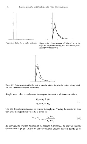
Figure 4.6a Pulse fed to buffer tank (ud. Figure 4.6b Pulse response of "charge" uc in the
capacitor for perfect mixing (thick line) and imperfect
mixing E=0.5 (thin line).
Figure 4.7 Outlet response of buffer tank to pulse in inlet to the pulse for perfect mixing (thick
line) and imperfect mixing E=0.5 (thin line).
Simple mass balance can be used to compute the reactor inlet concentrations:
The non-trivial impact comes on reactor throughput. Taking the reactor to have
unit area, the superficial velocity is given by:
By the way, the fraction retained in the recycle, f, might not be unity in case the
system needs a purge. It may be the case that the product take-off has the effect