
Page 155 - Process Modelling and Simulation With Finite Element Methods
P. 155
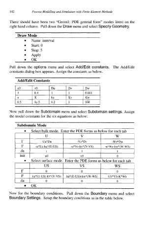
142        Process Modelling and Simulation with Finite Element Methods


          There  should have been two “Geoml: PDE general form” modes listed  on the
         right hand column.  Pull down the Draw menu and select Specify Geometry.

              Draw Mode
                     Name: interval
                     Start: 0
                     Stop: 5
                     Apply
                     OK
          Pull down the options menu and select Add/Edit constants.
          Pull  down  the  options menu  and  select  Add/Edit constants.  The  AddEdit
          constants dialog box appears. Assign the constants as below.

              AddLEdit Constants


                                                 0.001
                                                 Kw
              0.5      le-5    0.2               100

         Now pull
                                          and select
         the model constants for the six equations as below:


                            U                  V                 W
                r         -Uz*Du             -Vz*Dv            -w7*nw
                F   l  -u*Uz-ku*(U-US)  I  -u*Vz-kv*(V-VS)   -u*Wz-kw”(W-WS)
               da   1        1                 1                  1
            1               u0                 v0                0        1

                 0   Select surface mode.  Enter the PDE forms as below for each tab
                r           0                  0

                F    ku*(U-US)-kv*(V-VS)  ku*(U-US)+kw*(W-WS)  US *VS-K“ WS

                     OK
          Now  for  the  boundary  conditions.  Pull  down  the  Boundary menu  and  select
          Boundary Settings. Setup the boundary conditions as in the table below.