
Page 329 - Process Modelling and Simulation With Finite Element Methods
P. 329
316 Process Modelling and Simulation with Finite Element Methods
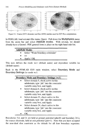
Figure 9.1 Coarse (2073 elements) and fine (8292) meshes used for ECT flux computations.
In FEMLAB, load ect.mat (file menu, Open). Pull down the Multiphysics menu
from the menu bar and select Add/Edit modes. With ect.mat, we should
already have a Geoml: PDE general form in place on the right hand side list.
Add/Edit Modes
Select “Weak boundary constraint”
0 >>
0 Apply/OK
This now defines the mode wcl (default name) and dependent variable lm
(default name).
Back in the FEMLAB GUI main window, select Boundary Mode and
Boundary Settings for mode wcl.
Boundary Mode and Boundary Settings (wcl)
Select domain 5, check active in this
subdomain, type ‘phi’ into the constraint
variable entry box, and Apply
Select domain 6, check active in this
subdomain, type ‘phi’ into the constraint
variable entry box, and Apply
Select domain 21, check active in this
subdomain, type ‘phi’ into the constraint
variable entry box, and Apply
Select domain 24, check active in this
subdomain, type ‘phi’ into the constraint
variable entry box, and Apply
OK
Boundaries 5,6, and 21 are held at ground potential (phi=O) and boundary 24 is
the source electrode, held at unit potential (phi=l). Note that you have accepted
the non-ideal dim constraint as the default for all four boundary segments.