
Page 198 - Programming Microcontrollers in C
P. 198
Timers 183
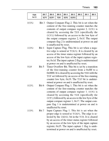
TSR Bit 7 Bit 6 Bit 5 Bit 4 Bit 3 Bit 2 Bit 1 Bit 0
0x13 ICF1 OCF1 TOV ICF2 OCF2
OCF2 Bit 3 Output Compare Flag 2. This bit is set when the
content of the free-running counter matches the
contents of output compare register 2. OCF2 is
cleared by accessing the TSR (specifically the
OCF2) followed by an access to the low byte of
the output compare register 2, 0x1f. The output
compare flag 2 is undetermined at power on and
is unaffected by reset.
ICF2 Bit 4 Input Capture Flag. This bit is set when a nega
tive edge is sensed at TCAP2. It is cleared by an
access of the timer status register followed by an
access of the low byte of the input capture regis
ter, 0x1d. The input capture 2 flag is undetermined
at power on and is unaffected by reset.
TOF Bit 5 Timer Overflow Bit. This bit is set by a transition
of the free-running counter from a 0xffff to a
0x0000. It is cleared by accessing the TSR with the
TOF set followed by an access of the free-running
counter low byte, 0x19. The TOF bit is undeter
mined at power on and is unaffected by reset.
OCF1 Bit 6 Output Compare Flag 1. This bit is set when the
content of the free-running counter matches the
contents of output compare register 1. OCF2 is
cleared by accessing the TSR (specifically the
OCF1) followed by an access to the low byte of the
output compare register 1, 0x17. The output com
pare flag 1 is undetermined at power on and is
unaffected by reset.
ICF1 Bit 7 Input Capture Flag 1. This bit is set when the
proper edge is sensed at TCAP1. The edge is se
lected by the IEDG1 bit in the TCR. It is cleared
by an access of the timer status register followed
by an access of the low byte of the input capture
register, 0x15. The input capture 1 flag is unde
termined at power on and is unaffected by reset.