
Page 117 - Radar Technology Encyclopedia
P. 117
DELAY delay line, acoustic-wave 107
DELAY DELAY LINE. A delay line is a device that provides tempo-
ral delay of signals. Such devices are used for temporal selec-
Group [envelope, instantaneous] delay is the delay of the
tion (gating), pulse measurements, matching the operation of
energy passing through a network, associated with a narrow
pulse devices, the separation of channels, in systems using
frequency band of signals. The usual notation is t . For exam-
g
ple, if the spectrum of the pulse going through a dispersive pulse compression, and in frequency-scanned arrays. The
basic parameters of a delay line are its time delay, passband,
network is relatively wide, the output pulse envelope will dif-
electromagnetic transmission coefficient (a loss for a passive
fer from that of the input one because the delay of the lower
delay line, or gain for an active delay line), and the spurious
frequency components will be different than the delay of the
signal level. Delay lines may be categorized as analog or dig-
higher frequency components. The phase delay and group
ital, the former being either electrical or acoustic. The great-
delay are equal only when there is no dispersion (i.e., when
est time delay is achieved with ultrasonic delay lines (up to
the carrier phase delay is linearly related to frequency). SAL
100 ms), and the least with coaxial cable delay lines (up to
Ref.: Wehner (1987), p. 52.
1 ms). The middle ground is occupied by electrical delay lines
Phase delay is the delay of the signal phase when it passes using the charge migration effect (up to 60 ms).
through a medium or network. For example, an input signal A particularly descriptive characteristic of a delay line is
of phase 2pf t + y , where f is the frequency and y is the the product of its time delay and bandwidth. The highest
i
i
4
input phase, exits the network with a phase of 2pf[t - product, up to 25 ´ 10 , is found in beam-type ultrasonic
t(f)] + y , where t(f) is the frequency-dependent phase delay lines, manufactured from piezoelectric monocrystals.
i
p
p
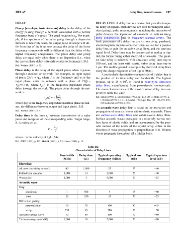
delay through the network. The phase delay through the net- The main characteristics of the most common delay lines are
work is given in Table D2. IAM
f f ()
t f () –= ---------- Ref.: IEEE (1993), p. 323; Skolnik (1970), pp. 20.3–20.15; Sloka (1970), p.
p 2pf 178; Fink (1975), p. 3-31; Brookner (1977), pp. 182, 185–186, 191–195,
where f(f) is the frequency-dependent insertion phase in radi- 384; Lukoshkin (1983), p. 217.
ans, the difference between output and input phase. SAL
An acoustic-wave delay line is based on the excitation and
Ref.: Wehner (1987), p. 51. propagation of acoustic waves within elastic materials. There
Delay time is the time t between transmission of a radar are surface-wave delay lines and volume-wave delay lines.
d
pulse and reception of the corresponding echo. Target range, Surface acoustic waves propagate in a relatively narrow sur-
R, is estimated as face layer of elastic solids and are accompanied by the peri-
2t d odic motion of the nodes of the crystal array, either in the
R = ------- direction of wave propagation or perpendicular to it. Volume
c
waves propagate throughout all a thicker body.
where c is the velocity of light. SAL
Ref.: IEEE (1993), p. 322; Skolnik (1962), p. 2; Leonov (1988), p. 13.
Table D2
Characteristics of Delay Lines
Bandwidth Delay time Typical operating Typical loss Typical spurious
(MHz) (ms) frequency (MHz) (dB) level (dB)
Electrical
All-pass time delay network 40 1,000 25 25 - 40
Folded-type meander 1,000 1.5 2,000 25 - 40
Waveguide 1,000 3 5,000 60 - 25
Acoustic wave
Strip:
aluminum 1 500 5 15 - 60
steel 20 350 45 70 - 55
Diffraction grating:
perpendicular 40 75 100 30 - 45
wedge 250 65 500 50 - 50
Acoustic surface wave 40 50 100 70 - 50
Yttrium-iron-garnet (YIG) 1,000 10 2,000 70 - 20